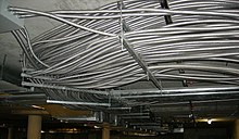
In the electrical wiring of buildings, a cable tray system is used to support insulated electric cables used for power distribution and communication. Cable trays are used as an alternative to open wiring or electrical conduit systems. Cable trays are commonly used for cable management in commercial and industrial construction. Cable trays are especially useful where changes to a wiring system are anticipated, since new cables can be installed by laying them in the tray, instead of pulling them through a pipe.
Several types of tray are used in different applications. A solid-bottom tray provides the maximum protection to cables, but requires cutting the tray or using fittings to enter or exit cables. A deep, solid enclosure for cables is called a cable channel or cable trough.
Types
A ventilated tray has openings in the bottom of the tray, allowing some air circulation around the cables, water drainage, and allows some dust to fall through the tray. Small cables may exit the tray through the ventilation openings, which may be slots or holes punched in the bottom. Ladder-type tray has the cables supported by a traverse bar, like the rungs of a ladder, at regular intervals on the order of 4 to 12 inches (100 to 300 mm).
Ladder and ventilated trays may have solid covers to protect cables from falling objects, dust, and water. Tray covers for use outdoors or very dusty locations may have a peaked shape to shed snow, ice or dust.
Where a great number of small cables are used, such as for telephone or computer network cables, lighter cable trays are appropriate. These may be made of wire mesh, called "cable basket", or may take the form of a single central spine (rail) with ribs to support cable on either side, a little like a fish spine and ribs.
Large power cables laid in tray may require support blocks to maintain spacing between conductors to prevent overheating of wires. Smaller cables may be laid unsecured in horizontal trays, or can be secured with cable ties to the bottom of vertically-mounted trays.
To maintain support of cables at changes of elevation or direction of a tray, a large number of specialized cable tray fittings are made compatible with each style (and manufacturer) of tray. Horizontal elbows change direction of a tray in the same plane as the bottom of the tray and are made in 30, 45 and 90 degree forms; inside and outside elbows are for changes perpendicular to the tray bottom. Tees, crosses, and other shapes exist. Some manufacturers and types provide adjustable elbows, useful for field-fitting a tray around obstacles or around irregular shapes.
Various clamping, supporting and splicing accessories are used with cable tray to provide a complete functional tray system. For example, different sizes of cable tray used within one run can be connected with reducers.
Materials used
Common cable trays are made of galvanized steel, stainless steel, aluminum, or glass-fiber reinforced plastic. The material for a given application is chosen based on the corrosion resistance required for the location.
Fire safety concerns and solutions
Combustible cable jackets may catch on fire and cable fires can thus spread along a cable tray within a structure. This is easily prevented through the use of fire-retardant cable jackets, orfireproofing coatings applied to installed cables. Heavy coatings or long fire-stops may require adjustment of the cable current ratings, since such fireproofing measures may reduce the heat dissipation of installed cables.
Proper housekeeping is important. Cable trays are often installed in hard to reach places. Combustible dust and clutter may accumulate if the trays are not routinely checked and kept clean.
Plastic and fibreglass reinforced plastic cable trays are combustible; the effect is mitigated through the use of fire retardants or fireproofing.
Ferrous cable trays expand with the increasing heat from accidental fire. This has been proven by the German Otto-Graf-Institut Test Report III.1-80999/Tei/tei "Supplementary Test On The Topic Of Mechanical Force Acting On Cable Penetration Firestop Systems During The Fire Test", dated 23 October 1984, to dislodge "soft" firestops, such as those made of fibrous insulations with rubber coatings. The same thing would apply to any silicone foam seals. This is easily remedied through the use of firestop mortars, as shown above, of sufficient compression strength and thickness. Also, some building codes mandate that penetrants, such as cable trays are installed to avoid their contribution to the collapse of a firewall.


