Minggu, 19 Juni 2011

Laporan Akhir Semester 4

Berikut adalah Laporan Akhir Semester 4 oleh Dio Meiwandany :


01 Area Kerja Router

02. Membangun PC Router

03. Membangun PC Router Menggunakan Ubuntu Server

04. Membanugn PC Router Menggunakan Mikrotik

05. Membanugn PC Router MenggunakanWindows, Mikrotik, dan Ubuntu Server

06. Packet Filtering

07. Open Proxy

08. Transparent Proxy

09. Observasi

Terima Kasih

Kamis, 31 Maret 2011

Serangan Logika Jaringan

Pada zaman sekarang, sudah tidak lazim lagi teknologi ada di lingkungan kita. Apalagi untuk masalah koneksi, pastinya sudah umum di dengar.
Nah, dimana terdapat koneksi, disitu juga terdapat kelemahannya. Kelemahan-kelemahan tersebut biasanya di manfaatkan oleh oknum-oknum yang inginmenggunakan, bahkan menyerang sistem jaringan tersebut.


Kali ini, saya akan membahas tentang beberapa Serangan Logika Jaringan tersebut.

Jumat, 04 Februari 2011

PC Router


I. TUJUAN

a. Siswa dapat memahami PC Router dan mengetahui spesifikasi minimal dari os yang akan digunakan.

b. Siswa dapat membangun sebuah PC Router menggunakan OS Free BSD.

II. PENDAHULUAN

PC Router merupakan Router yang di buat dari sebuah PC yang dijadikan Fungsi Router yang dijalakan dengan sistem operasi dan kebanyakan sistem operasi yang digunakan adalah berbasis OS (Operation System) Linux sehingga biasa di sebut Linux Based Router.
PC Router atau Linux Based Router sebenarnya sangat banyak sekali variannya baik yang berbayar/komersil maupun yang Free/open source.
Yang komersil seperti Mikrotik OS, LogixOS/Neology, Gibraltar Dll, dan yang

Free/open source seperti MonoWall, Pfsense, Smothwall Express, IPCop, Linktrack,
DD-WrtX86, OpenWRTX86, Freesco dan masih banyak lagi lainnya.

FreeBSD adalah sebuah sistem operasi bertipe Unix bebas yang diturunkan dari
UNIX AT&T lewat cabang Berkeley Software Distribution (BSD) yaitu sistem operasi

386BSD dan 4.4BSD. FreeBSD berjalan di atas sistem Intel x86 (IA-32) (termasuk
Microsoft Xbox[1], DEC Alpha   , Sun UltraSPARC       , IA-64   , AMD64     , PowerPC dan arsitektur
NEC PC-98   . Dukungan untuk arsitektur ARM dan MIPS sedang dalam pengembangan,

FreeBSD dapat berjalan diberbagai mesin contoh Intel X86 ( 32‐bit dan64‐bit),
ProsesorCompac/Digital Alpha, MesinSPARC 64 –bit dariSun Microsystem, PowerPC,

AMD64. FreeBSD merupakan turunan dari Berkeley UNIX. Akan tetapi, FreeBSD tidak
bisa dipanggil sebagai Unix.
Untuk Laporan, dapat dilihat di http://www.scribd.com/doc/48132734

Kamis, 20 Januari 2011

Firewall

Pada pembahasan kali ini, saya akan menerangkan tentang materi Firewall.

Firewall adalah suatu cara atau mekanisme yang diterapkan baik terhadap hardware, software ataupun sistem itu sendiri dengan tujuan untuk melindungi, baik dengan menyaring, membatasi atau bahkan menolak suatu atau semua hubungan/kegiatan pada jaringan pribadi dengan jaringan luar yang bukan merupakan ruang lingkupnya.

  • Jenis Firewall sendiri pun ada 2 macam, yaitu :

- Personal Firewall
Personal Firewall adalah pembatasan suatu aplikasi yang ada pada PC atau laptop untuk terhubung ke jaringan dari akses yang tidak ingin dikehendaki. Biasanya firewall jenis ini sudah terintegrasi pada kalangan Windows, contohnya Windows XP dan Windows Vista.
Secara umum hanya memiliki 2 fitur utama, yaitu Packet Filter Firewall dan Stateful Firewall.

- Network Firewall
Network Firewall adalah Firewall yang didesain untuk melindungi jaringan secara keseluruhan dari berbagai serangan. Umumnya dijumpai dalam dua bentuk, yakni sebuah perangkat terdedikasi atau sebagai sebuah perangkat lunak yang diinstalasikan dalam sebuah server.
Network Firewall secara umum memiliki beberapa fitur utama, yakni apa yang dimiliki oleh personal firewall (packet filter firewall dan stateful firewall), Circuit Level Gateway, Application Level Gateway, dan juga NAT Firewall. Network Firewall umumnya bersifat transparan (tidak terlihat) dari pengguna dan menggunakan teknologi routing untuk menentukan paket mana yang diizinkan, dan mana paket yang akan ditolak.

Selasa, 26 Oktober 2010

Cable Tray

In the electrical wiring of buildings, a cable tray system is used to support insulated electric cables used for power distribution and communication. Cable trays are used as an alternative to open wiring or electrical conduit systems. Cable trays are commonly used for cable management in commercial and industrial construction. Cable trays are especially useful where changes to a wiring system are anticipated, since new cables can be installed by laying them in the tray, instead of pulling them through a pipe.
Several types of tray are used in different applications. A solid-bottom tray provides the maximum protection to cables, but requires cutting the tray or using fittings to enter or exit cables. A deep, solid enclosure for cables is called a cable channel or cable trough.

Types

A ventilated tray has openings in the bottom of the tray, allowing some air circulation around the cables, water drainage, and allows some dust to fall through the tray. Small cables may exit the tray through the ventilation openings, which may be slots or holes punched in the bottom. Ladder-type tray has the cables supported by a traverse bar, like the rungs of a ladder, at regular intervals on the order of 4 to 12 inches (100 to 300 mm).
Ladder and ventilated trays may have solid covers to protect cables from falling objects, dust, and water. Tray covers for use outdoors or very dusty locations may have a peaked shape to shed snow, ice or dust.

Where a great number of small cables are used, such as for telephone or computer network cables, lighter cable trays are appropriate. These may be made of wire mesh, called "cable basket", or may take the form of a single central spine (rail) with ribs to support cable on either side, a little like a fish spine and ribs.
Large power cables laid in tray may require support blocks to maintain spacing between conductors to prevent overheating of wires. Smaller cables may be laid unsecured in horizontal trays, or can be secured with cable ties to the bottom of vertically-mounted trays.
To maintain support of cables at changes of elevation or direction of a tray, a large number of specialized cable tray fittings are made compatible with each style (and manufacturer) of tray. Horizontal elbows change direction of a tray in the same plane as the bottom of the tray and are made in 30, 45 and 90 degree forms; inside and outside elbows are for changes perpendicular to the tray bottom. Tees, crosses, and other shapes exist. Some manufacturers and types provide adjustable elbows, useful for field-fitting a tray around obstacles or around irregular shapes.
Various clamping, supporting and splicing accessories are used with cable tray to provide a complete functional tray system. For example, different sizes of cable tray used within one run can be connected with reducers.


Materials used

Common cable trays are made of galvanized steel, stainless steel, aluminum, or glass-fiber reinforced plastic. The material for a given application is chosen based on the corrosion resistance required for the location.


Fire safety concerns and solutions

Combustible cable jackets may catch on fire and cable fires can thus spread along a cable tray within a structure. This is easily prevented through the use of fire-retardant cable jackets, orfireproofing coatings applied to installed cables. Heavy coatings or long fire-stops may require adjustment of the cable current ratings, since such fireproofing measures may reduce the heat dissipation of installed cables.
Proper housekeeping is important. Cable trays are often installed in hard to reach places. Combustible dust and clutter may accumulate if the trays are not routinely checked and kept clean.
Plastic and fibreglass reinforced plastic cable trays are combustible; the effect is mitigated through the use of fire retardants or fireproofing.
Ferrous cable trays expand with the increasing heat from accidental fire. This has been proven by the German Otto-Graf-Institut Test Report III.1-80999/Tei/tei "Supplementary Test On The Topic Of Mechanical Force Acting On Cable Penetration Firestop Systems During The Fire Test", dated 23 October 1984, to dislodge "soft" firestops, such as those made of fibrous insulations with rubber coatings. The same thing would apply to any silicone foam seals. This is easily remedied through the use of firestop mortars, as shown above, of sufficient compression strength and thickness. Also, some building codes mandate that penetrants, such as cable trays are installed to avoid their contribution to the collapse of a firewall.
Conduit

An electrical conduit is an electrical piping system used for protection and routing of electrical wiring. Electrical conduit may be made of metal, plastic, fiber, or fired clay. Flexible conduit is available for special purposes.
Conduit is generally installed by electricians at the site of installation of electrical equipment. Its use, form, and installation details are often specified by wiring regulations, such as the U.S. NEC or other national or local code. The term "conduit" is commonly used by electricians to describe any system that contains electrical conductors, but the term has a more restrictive definition when used in wiring regulations.
Early electric lighting installations made use of existing gas pipe to gas light fixtures (converted to electric lamps). Since this technique provided very good protection for interior wiring, it was extended to all types of interior wiring and by the early 20th century purpose-built couplings and fittings were manufactured for electrical use.


Comparison with other wiring methods

Electrical conduit provides very good protection to enclosed conductors from impact, moisture, and chemical vapors. Varying numbers, sizes, and types of conductors can be pulled into a conduit, which simplifies design and construction compared to multiple runs of cables or the expense of customised composite cable. Wiring systems in buildings are subject to frequent alterations. Frequent wiring changes are made simpler and safer through the use of electrical conduit, as existing conductors can be withdrawn and new conductors installed, with little disruption along the path of the conduit. A conduit system can be made waterproof or submersible. Metal conduit can be used to shield sensitive circuits from electromagnetic interference, and also can prevent emission of such interference from enclosed power cables.
When installed with proper sealing fittings, a conduit will not permit the flow of flammable gases and vapors, which provides protection from fire and explosion hazard in areas handling volatile substances.
Some types of conduit are approved for direct encasement in concrete. This is commonly used in commercial buildings to allow electrical and communication outlets to be installed in the middle of large open areas. For example, retail display cases and open-office areas use floor-mounted conduit boxes to connect power and communications cables.
Both metal and plastic conduit can be bent at the job site to allow a neat installation without excessive numbers of manufactured fittings. This is particularly advantageous when following irregular or curved building profiles.
The cost of conduit installation is higher than other wiring methods due to the cost of materials and labor. In applications such as residential construction, the high degree of physical damage protection is not required so the expense of conduit is not warranted. Conductors installed within conduit cannot dissipate heat as readily as those installed in open wiring, so the current capacity of each conductor must be reduced if many are installed in one conduit. It is impractical, and prohibited by wiring regulations, to have more than 360 degrees of total bends in a run of conduit, so special outlet fittings must be provided to allow conductors to be installed without damage in such runs. While metal conduit can be used as a grounding conductor, the circuit length is limited. A long run of conduit as grounding conductor will not allow proper operation of overcurrent devices on a fault, for example.

Types of conduit

Conduit systems are classified by the wall thickness, mechanical stiffness, and material used to make the tubing.


Rigid Metal Conduit (RMC)

Rigid Metal Conduit (RMC) is a thick threaded tubing, usually made of coated steel, stainless steel or aluminum.


Rigid Nonmetallic Conduit (RNC)

Rigid Nonmetallic Conduit (RNC) is a non-metallic unthreaded tubing.


Galvanized rigid conduit (GRC)

Galvanized rigid conduit (GRC) is galvanized steel tubing, with a tubing wall that is thick enough to allow it to be threaded. Its common applications are in commercial and industrial construction.


Electrical metallic tubing (EMT)
Electrical Metallic tubing (EMT), sometimes called thin-wall, is commonly used instead of galvanized rigid conduit (GRC), as it is less costly and lighter than GRC. EMT itself may not be threaded, but can be used with threaded fittings that clamp to it. Lengths of conduit are connected to each other and to equipment with clamp-type fittings. Like GRC, EMT is more common in commercial and industrial buildings than in residential applications. EMT is generally made of coated steel, though it may be aluminum.


Electrical Nonmetallic Tubing (ENT)

Electrical Nonmetallic Tubing (ENT) is a thin-walled corrugated tubing that is moisture-resistant and flame retardant. It is pliable such that it can be bent by hand and is often flexible although the fittings are not. It is not threaded due to its corrugated shape although the fittings might be.

Flexible Metallic Conduit (FMC)


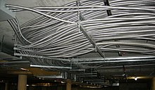
Flexible metallic conduit used in an underground parking facility.
Flexible Metallic Conduit (FMC) is made through the coiling of a self-interlocked ribbed strip of aluminum or steel, forming a hollow tube through which wires can be pulled. FMC is used primarily in dry areas where it would be impractical to install EMT or other non-flexible conduit, yet where metallic strength to protect conductors is still required. The flexible tubing does not maintain any permanent bend.
Cutting FMC requires a specialized hand tool with a rotary abrasive disc to creates a small incision into the ribbing so that a twisting motion separates the segments. The disc cuts deep enough to sever the armor coil but not so deep that it could damage the inside conductors.
Short segments of FMC called whips are often used as circuit "pigtails" between fixtures and ajunction box, especially in suspended ceilings. Whip assemblies save a great deal of repetitive labor when installations require several pigtails for several fixtures.
Flexible metal conduit coated with a UV-resistant polymer is liquid-tight when installed with appropriate glandular fittings containing liquid-tight features such as O-rings.
Wiring regulations vary; in locales following the U.S. National Electric Code (NEC), flexible metallic conduit may serve as an equipment-grounding conductor. Other areas may require a bonding wire for equipment grounding. The bonding wire in direct contact with the interior of the conduit creates a lower resistance grounding conductor than the conduit alone.

Liquidtight Flexible Metal Conduit (LFMC)

Liquidtight Flexible Metal Conduit (LFMC) is a metallic flexible conduit covered by a waterproof plastic coating. The interior is similar to FMC.


Flexible Metallic Tubing (FMT)

Flexible Metallic Tubing (FMT) is not the same as Flexible Metallic Conduit (FMC) aka "greenfield" or "flex" which is National Electrical Code (NEC) Art 348. FMT is a raceway, but not a conduit and is a separate NEC Article - 360. It only comes in 1/2" & 3/4" trade sizes whereas FMC is sized 1/2" ~ 4" trade sizes. NEC 360.2 describes it as: "A raceway that is circular in cross section, flexible, metallic and liquidtight without a nonmetallic jacket."


Liquidtight Flexible Nonmetallic Conduit (LFNC)

Liquidtight Flexible Nonmetallic Conduit (LNFC) refers to several types of flame-resistant non-metallic tubing. Interior surfaces may be smooth or corrugated. There may be integral reinforcement within the conduit wall. It is also known as FNMC.


Aluminum conduit

Aluminum conduit, similar to galvanized steel conduit, is a rigid conduit, generally used in commercial and industrial applications, where a higher resistance to corrosion is needed. Such locations would include food processing plants, where large amounts of water and cleaning chemicals would make galvanized conduit unsuitable. Aluminum cannot be directly embedded in concrete, since the metal reacts with thealkalis in cement. The conduit may be coated to prevent corrosion by incidental contact with concrete. The extra cost of aluminum is somewhat offset by the lower labor cost to install, since a length of aluminum conduit will have about one-third the weight of an equally-sized rigid steel conduit.


Intermediate metal conduit (IMC)

Intermediate Metal Conduit (IMC) is a steel tubing heavier than EMT but lighter than RMC. It may be threaded.


PVC conduit

PVC conduit is the lightest in weight compared to other conduit materials, and usually lower in cost than other forms of conduit. In North American electrical practice, it is available in three different wall thicknesses, with the thin-wall variety only suitable for embedded use in concrete, and heavier grades suitable for direct burial and exposed work. The various fittings made for metal conduit are also made for PVC. The plastic material resists moisture and many corrosive substances, but since the tubing is non-conductive an extra bonding (grounding) conductor must be pulled into each conduit. PVC conduit may be heated and bent in the field. Joints to fittings are made with slip-on solvent-welded connections,which set up rapidly after assembly and attain full strength in about one day. Since slip-fit sections do not need to be rotated during assembly, the special union fittings used with threaded conduit (Ericson) are not required. Since PVC conduit has a higher thermal coefficient of expansion than other types, it must be mounted so as to allow for expansion and contraction of each run. Care should be taken when installing PVC underground in multiple or parallel run configurations due to mutual heating effect of cable

Other metal conduits

In extreme corrosion environments where plastic coating of the tubing is insufficient, conduits may be made from stainless steel, bronze or brass.


Underground conduit

Large diameter (more than 2 inch/50 mm) conduit may be installed underground between buildings to allow installation of power and communication cables. An assembly of these conduits, often called a duct bank, may either be directly buried in earth or encased in concrete. A duct bank will allow replacement of damaged cables between buildings or additional power and communications circuits to be added, without the expense of excavation of a trench. While metal conduit is occasionally used for burial, usually PVC, polyethylene or polystyrene plastics are now used due to lower cost. Formerly, compressed asbestos fiber mixed with cement was used for some underground installations. Telephone and communications circuits were installed in fired-clay conduit.


Comparison of some types of conduit

Relative to rigid galvanized steel conduit, 3/4 inch (21 metric) size
RelativeRGSAluminumIMCEMTPVC
Labor1.00.890.890.620.55
Weight1.00.340.760.420.20
Material cost1.00.990.840.350.43
Exact ratios of installation labor, weight and material cost vary depending on the size of conduit, but the values for 3/4 inch (21 metric) trade size are representative.


Other wireways


Surface Mounted Raceway (wire molding)

This type of "decorative" conduit is designed to provide an aesthetically acceptable passageway for wiring without hiding it inside or behind a wall. This is used where additional wiring is required, but where going through a wall would be difficult or require remodeling. The conduit has an open face with removable cover, secured to the surface, and wire is placed inside. Plastic raceway is often used for telecommunicationwiring, such as network cables in an older structure, where it is not practical to drill through concrete block.
Advantages
  • It allows one to add new wiring to an existing building without removing or cutting holes into the drywall or lath and plaster.
  • It allows circuits to be easily locatable and accessible for future changes thus enabling minimum effort upgrades.
Disadvantages
  • Its appearance may not be acceptable to all observers.


Trunking

The term trunking is used in the United Kingdom for electrical wireways , generally rectangular in cross section with removable lids.
Mini Trunking is a term used in the UK for small form-factor (usually 6mm to 25mm square or rectangle sectioned) PVC wire ways.
In North American practice "wire trough" or "lay-in wireways" are terms used to designate similar products, but these are never used enclosed in masonry or a wall.


Passive fire protection

Conduit is of relevance to both firestopping, where they become penetrants, and fireproofing, where circuit integrity measures can be applied on the outside to keep the internal cables operational during an accidental fire. The British standard BS476 also considers internal fires, whereby the fireproofing must protect the surroundings from cable fires. Any external treatments must consider the effect upon ampacity derating.

Kamis, 21 Oktober 2010

VLSM (Variable Length Subnet Mask)

VLSM (Variable Length Subnet Mask) Vlsm adalah pengembangan mekanisme subneting, dimana dalam vlsm dilakukan peningkatan dari kelemahan subneting klasik, yang mana dalam clasik subneting, subnet zeroes, dan subnet- ones tidak bisa digunakan. selain itu, dalam subnet classic, lokasi nomor IP tidak efisien.

Perhitungan IP Address menggunakan metode VLSM adalah metode yang berbeda dengan memberikan suatu Network Address lebih dari satu subnet mask, jika menggunakan CIDR dimana suatu Network ID hanya memiliki satu subnet mask saja, perbedaan yang mendasar disini juga adalah terletak pada pembagian blok, pembagian blok VLSM bebas dan hanya dilakukan oleh si pemilik Network Address yang telah diberikan kepadanya atau dengan kata lain sebagai IP address local dan IP Address ini tidak dikenal dalam jaringan internet, namun tetap dapat melakukan koneksi kedalam jaringan internet, hal ini terjadi dikarenakan jaringan internet hanya mengenal IP Address berkelas.
Metode VLSM ataupun CIDR pada prinsipnya sama yaitu untuk mengatasi kekurangan IP Address dan dilakukannya pemecahan Network ID guna mengatasi kekerungan IP Address tersebut. Network Address yang telah diberikan oleh lembaga IANA jumlahnya sangat terbatas, biasanya suatu perusahaan baik instansi pemerintah, swasta maupun institusi pendidikan yang terkoneksi ke jaringan internet hanya memilik Network ID tidak lebih dari 5 – 7 Network ID (IP Public).
Dalam penerapan IP Address menggunakan metode VLSM agar tetap dapat berkomunikasi kedalam jaringan internet sebaiknya pengelolaan network-nya dapat memenuhi persyaratan ; routing protocol yang digunakan harus mampu membawa informasi mengenai notasi prefix untuk setiap rute broadcastnya (routing protocol : RIP, IGRP, EIGRP, OSPF dan lainnya, bahan bacaan lanjut protocol routing : CNAP 1-2), semua perangkat router yang digunakan dalam jaringan harus mendukung metode VLSM yang menggunakan algoritma penerus packet informasi.
Tahapan perihitungan menggunakan VLSM IP Address yang ada dihitung menggunakan CIDR selanjutnya baru dipecah kembali menggunakan VLSM, sebagai contoh :
130.20.0.0/20
Kita hitung jumlah subnet terlebih dahulu menggunakan CIDR, maka didapat
11111111.11111111.11110000.00000000 = /20
Jumlah angka binary 1 pada 2 oktat terakhir subnet adalah 4 maka
Jumlah subnet = (2x) = 24 = 16
Maka blok tiap subnetnya adalah :
Blok subnet ke 1 = 130.20.0.0/20
Blok subnet ke 2 = 130.20.16.0/20
Blok subnet ke 3 = 130.20.32.0/20
Dst ... sampai dengan
Blok subnet ke 16 = 130.20.240.0/20
Selanjutnya kita ambil nilai blok ke 3 dari hasil CIDR yaitu 130.20.32.0 kemudian :
- Kita pecah menjadi 16 blok subnet, dimana nilai 16 diambil dari hasil perhitungan
subnet pertama yaitu /20 = (2x) = 24 = 16
Selanjutnya nilai subnet di ubah tergantung kebutuhan untuk pembahasan ini kita
gunakan /24, maka didapat 130.20.32.0/24 kemudian diperbanyak menjadi 16
blok lagi sehingga didapat 16 blok baru yaitu :
Blok subnet VLSM 1-1 = 130.20.32.0/24
Blok subnet VLSM 1-2 = 130.20.33.0/24
Blok subnet VLSM 1-3 = 130.20.34.0/24
Blok subnet VLSM 1-4 = 130.20.35.0/24
Dst ... sampai dengan
Blok subnet VLSM 1-16 = = 130.20.47/24
- Selanjutnya kita ambil kembali nilai ke 1 dari blok subnet VLSM 1-1 yaitu
130.20.32.0 kemudian kita pecah menjadi 16:2 = 8 blok subnet lagi, namun oktat
ke 4 pada Network ID yang kita ubah juga menjadi 8 blok kelipatan dari 32
sehingga didapat :
Blok subnet VLSM 2-1 = 130.20.32.0/27
Blok subnet VLSM 2-2 = 130.20.32.32/27
Blok subnet VLSM 2-3 = 130.20.33.64/27
Blok subnet VLSM 2-4 = 130.20.34.96/27
Blok subnet VLSM 2-5 = 130.20.35.128/27
Blok subnet VLSM 2-6 = 130.20.36.160/27
Blok subnet VLSM 2-1 = 130.20.37.192/27
Blok subnet VLSM 2-1 = 130.20.38.224/27
Metode VLSM hampir serupa dengan CIDR hanya blok subnet hasil daro CIDR dapat kita
bagi lagi menjadi sejumlah Blok subnet dan blok IP address yang lebih banyak dan lebih
kecil lagi. Demikian pembahasan CIDR dan VLSM semoga bermanfaat.

Sumber : http://www.ilmukomputer.org/wp-content/uploads/2007/12/metode-ip-address-lanjutan-vlsm.pdf